05. SDevice Bias Setup
이 단계에서 확인할 내용
| Item | Description |
|---|---|
| Purpose | pMOS transfer curve를 얻기 위한 음전압 bias 구성 |
| Method | drain bias 설정 후 gate voltage를 0 V에서 음의 방향으로 sweep |
| Bias | Vd = -0.05, -1.0 V / Vg = -2.5 V |
| Output | enhancement-mode pMOS Id–Vg curve |
| Source | pmos_bias_sweep.cmd |
Bias Command
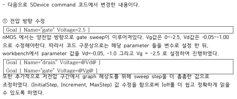
Figure. Workbench parameter를 이용한 pMOS drain/gate bias 설정.
Goal { Name="drain" Voltage=@Vd@ }
Goal { Name="gate" Voltage=@Vg@ }
Workbench에서는 다음 조건을 사용했습니다.
Vd = -0.05 V, -1.0 V
Vg = -2.5 V
gate sweep의 InitialStep, Increment, MaxStep도 조정해 Vg = 0 V와 -2.5 V 부근의 sampled point가 목표 bias에 충분히 가깝도록 구성했습니다.
Transfer Curve Verification
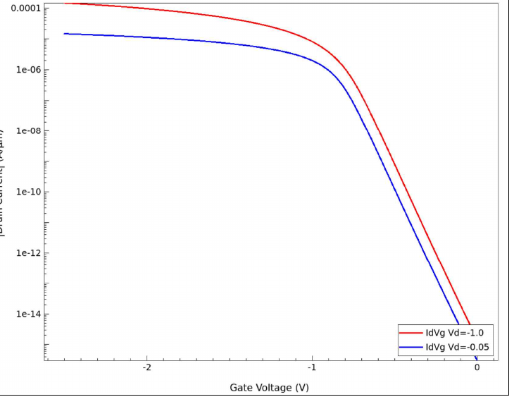
Figure. 두 drain bias에서 얻은 pMOS transfer curve.
Off-state
Vg가 0 V에 가까울 때 current가 매우 작아 pMOS가 off 상태에 있음을 확인했습니다.
Turn-on
Vg가 음의 방향으로 증가할수록 |Id|가 증가해 hole channel이 형성되는 방향과 일치했습니다.
Drain Bias
Vd = -1.0 V에서 Vd = -0.05 V보다 높은 current가 나타났습니다. 최종 성능 비교는 Vd = -1.0 V 조건을 기준으로 진행했습니다.
Verification Result
- negative Vtgm 확인
- Vg = -2.5 V에서 충분한 Ion 확인
- Vg = 0 V에서 낮은 Ioff 확인
- pMOS transfer direction 정상 확인
다음 단계에서는 이 curve에서 metric을 자동 추출했습니다.
Next: SVisual Metric Extraction
Summary:
Negative drain and gate sweeps were configured to verify enhancement-mode pMOS operation and provide consistent data for automatic metric extraction.